 Recessed Light Calculator
FIXTURE STRUCTURE FIELD GUIDE
Can vs. Canless Recessed Lighting: What Changes Above the Ceiling
A can light uses a recessed housing as part of its assembly. A canless light can use a different architecture, often a thin direct-mount module with a separate junction box or driver. Neither label tells you the complete fit, optical output, rating, or service path.
START WITH THE ASSEMBLY
- Can / housing
- One installed component
- Canless
- Architecture, not one shape
- Wafer
- Common thin form, not every canless light
- Decision
- Exact model + instructions
Compare documentation for the housing, module or trim, junction box/driver, accessories and ceiling condition together.
The Difference Is the Assembly, Not a Brightness Class
Choose between a housing-based or canless assembly after you know the ceiling condition and the exact product system. A recessed housing may support a compatible trim or retrofit module. A direct-mount canless product may avoid a full housing but still needs a specified cutout, junction box or driver location, support method and clearance. Do not assume either option is automatically brighter, cheaper, more efficient, shallower, or easier to service.
“Wafer” is commonly used for a thin, direct-mount LED style. It is useful search language, but it is not a technical category that makes every canless fixture identical. Some products called canless have different optics, controls, drivers, mounting hardware, or above-ceiling requirements. Read the current documentation for the actual catalog number and configuration.
Compare What Occupies the Ceiling Cavity
A structure comparison starts with components and locations. It does not substitute for the product drawing or tell you whether a particular joist bay, insulation condition, or existing opening will work.
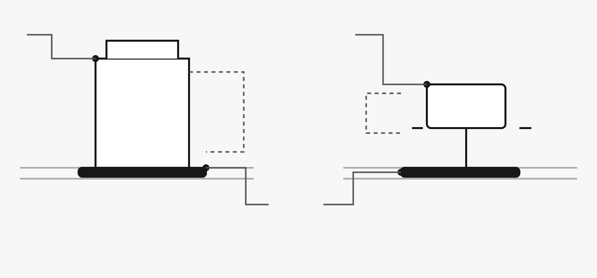
- Housing-based recessed assembly
- A housing can remain above the opening; the light module or trim must be one of the components permitted for that housing.
- Thin direct-mount assembly
- A thin ceiling-face module may place its junction box or driver beside the opening. Its box, cable route, supports, cutout and clearance still require the exact instructions.
Housing-based “can”
A new-construction or remodel housing is part of the recessed luminaire. The chosen trim, lamp or LED module must be identified as compatible with that housing. For example, HALO’s LT56 documentation describes specific 5- and 6-inch housing families and connection methods; a similar visible diameter alone is not the compatibility test.
Canless / direct mount
A thin module can reduce the depth immediately above the ceiling opening, but it does not erase the enclosure and wiring work. HALO HLB instructions, for example, specify the cutout and show a junction box for that product family. Treat those details as product-specific, rather than a promise about all thin fixtures.
For either architecture, first document the actual opening, trim, body or box envelope, and clearance requirements. A nominal aperture is neither a cutting template nor a lighting-layout rule.
Maintenance Depends on the Replaceable Part and the Access Route
Before comparing serviceability, ask what can actually be replaced: a lamp, a trim/module, a driver, a junction-box connection, or the whole listed assembly. The answer differs by product and installation—not simply by the word “canless.”
If the installed product has an identified removable screw-base lamp, use the recessed-bulb identification and replacement guide. A trim/module or integrated LED face follows its own product service instructions, not the bulb-change sequence.
- Existing housing with a compatible retrofit module: the housing can remain in the ceiling while an approved module is connected and retained inside it. That does not make an arbitrary replacement module compatible.
- Direct-mount thin module: its driver or junction box may be above the ceiling and accessible only through the opening or another approved access route. Check the instructions for disconnection, support and replacement before closing the ceiling.
- Unknown existing fixture: record all labels and inspect only as directed after power is off. If the assembly or wiring condition is uncertain, stop rather than choosing a replacement by face diameter.
Product instructions set the service method. HALO’s LT56 instructions distinguish retrofit connection methods for specified housing types, while the HLB instructions call out the product’s own junction-box and mounting sequence. Those examples illustrate why “same opening” is not enough to predict maintenance steps.
A Purchase Checklist That Separates Fit From Lighting
Make two lists. One answers whether the exact assembly can be installed and maintained in this ceiling; the other answers whether it produces the light and controls you need. Do not use a convenient installation label to answer both lists.
| Check | What to verify | Why it stays separate |
|---|---|---|
| Existing condition | Existing housing or open ceiling; cutout; ceiling thickness; accessible cavity; joists, ducts and wiring | These determine the viable installation paths, not light output. |
| Complete assembly | Housing, trim/module, driver or junction box, connectors and required accessories | Listing and compatibility language commonly applies to a stated combination. |
| Rating and environment | Insulation/contact conditions, airtight claim, damp/wet location, ceiling type and any local requirements | These are separate attributes. An IC, airtight or wet claim must come from the exact assembly’s documentation. |
| Optics and controls | Delivered lumens, distribution or beam data, color setting, dimmer/control compatibility and voltage | A thin profile or housing does not predict brightness, glare, color quality or dimmer behavior. |
| Future work | Approved removal/replacement procedure and the access route to connections or driver | Serviceability is a property of the installed system, not a universal can-versus-canless advantage. |
Use the spec-sheet guide to match lumens, watts and distribution to one exact fixture setting. Use the selected product data—not fixture architecture alone—when entering a room plan in the calculator.
Choose the Next Check for Your Situation
If you are replacing something already installed, identify its housing and connection first. If you are planning a new ceiling, map the full cavity and select an assembly before committing to opening locations. In either case, choose lighting output and distribution only after the fit and rating questions have a documented answer.
| Your situation | Collect first | Next check |
|---|---|---|
| Keep an existing labelled housing | Housing model, permitted trim/module combination and connection instructions. | Identify and measure the existing assembly, then shortlist only its documented compatible replacements. |
| New locations in a shallow or obstructed cavity | Body and box envelopes, joist/duct position, support and cable access—not only module thickness. | Compare complete mounting envelopes for the exact housing-based and direct-mount candidates. |
| Replacing a failed integrated LED | Which part the maker permits replacing; matching module/driver number, connector, available parts and service route. | Check serviceable parts and access. Confirm any matched replacement rather than substituting a universal driver or a look-alike light. |
| Insulation or shower exposure is relevant | Separate insulation-contact and location conditions for the complete selected assembly. | Check IC and component scope; assess wet-location exposure independently. |
Replacing an existing light
Start with the measurement and identification sequence. A compatible retrofit can be a valid path, but it requires the existing housing and the exact replacement instructions to match.
Planning new locations
Use the fixture worksheet to compare the complete assembly, then use verified lumens and distribution in the calculator as a general-lighting starting point.
The calculator estimates count and layout from disclosed room and fixture inputs. It does not select a housing, approve a direct-mount assembly, inspect a ceiling cavity, or validate electrical work.
Sources and Scope
Maintained by Recessed Light Calculator. This page is an explanatory comparison, not a product test or installation instruction. The diagram is an original component-location illustration; it is not drawn to scale or a manufacturer-approved installation detail.
- HALO Canless Direct Mount Design Guide — manufacturer category overview; use it to identify the product architecture, then confirm the installation instructions for the exact catalog number.
- HALO HLB-3 / HLB-4 / HLB-6 installation instructions — direct-mount product-family example: cutout, junction box, mounting and safety information; accessed October 14, 2026.
- HALO LT56 product record — example compatibility language for specified 5- and 6-inch housing families.
- HALO LT56 installation instructions — example retrofit connector and torsion-spring sequence for identified housing types.
- HALO Remodel Housings — example housing-based remodel category and linked documentation.
Recheck the current documentation for the exact model, accessory, ceiling condition and location before purchase or installation. For this site’s model assumptions, see Method & sources; to report a correction, use Contact.